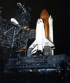
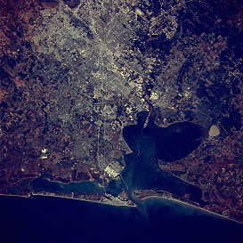
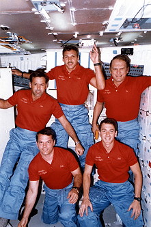
Launch from Cape Canaveral (
KSC) and
landing on Edwards
AFB, Runway 23.
The launch was postponed for
22 minutes and 30 seconds due to a main engine liquid hydrogen prevalve close
remote power controller showing a faulty 'on' indication.
This was the
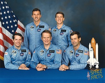
second Shuttle mission dedicated to Department of Defense, and most
information about it remained classified. For the second time,
NASA did not provide pre-launch commentary to the
public until nine minutes before liftoff. William
Pailes became as
MSE the second military astronaut in space. The crew
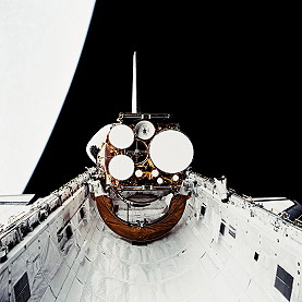
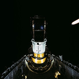
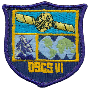
deployed two military communications satellites
DSCS III (USA-11 and USA-12). Both were launched
into stationary orbits by an Inertial Upper Stage. The
DSCS satellites used X-band frequencies (8/7 GHz).
Each
DSCS-III satellite had a design life of ten years,
although several of the
DSCS satellites have far exceeded their design life
expectancy.
DSCS-III spacecraft weighed 2,580 pounds. The
spacecraft's rectangular body was 6 feet x 6 feet x 7 feet (1.8 x 1.8 x 2.1
meters); with a 38-foot (11.5 meters) span with solar arrays deployed. Phase
III solar arrays generated 1,100 watts, decreasing to 837 watts after five
years. Each
DSCS III satellite costs about $100,000,000.
The
DSCS III satellites provided substantial capability to
support high-capacity links between all terminals and to permit AJ
communications and control of the satellites during crisis and contingency
situations.
DSCS III satellites operate in the X-band region,
providing uplink services in the 7900-8400 MHz band and downlink services in
the 7250-7750 MHz band. The frequency spectrum is divided into six bands by the
use of six limited-bandwidth transponders which are switchable between antennas
by
DSCS ground control. Communications performance is
optimized by allowing these independent transponders to be connected to various
types of antennas. This permits selection of Earth coverage (EC), area coverage
(AC), spot coverage, grouping of channels with similar modulation, and antenna
gain-to-noise temperature (G/ T) ratios to meet user needs. Any type of
modulation or multiple access may be used since the transponders do not process
or modulate the signals. The
DSCS III satellites are three-axis stabilized
(geostationary) vehicles that have a dry weight of 1,950 pounds (884 kg) and a
maximum weight of 2,550 pounds (1,156 kg) with propellant. The dimensions of
the satellite body are approximately 80 inches (6.5 feet or 1.98 meter) on each
side and 460 inches (38 feet or 11.58 meters) in length, with solar arrays (SA)
deployed. Communications antennas include a receive 61-beam multibeam antenna
(MBA) and two transmit 19-beam MBAs, two receive and two transmit Earth
coverage horns (ECH), and a transmit-only gimballed dish antenna (GDA). In
addition, there is one transmit and one receive SCT UHF antenna.
The
DSCS III Communications Subsystem includes six
independent RF channels, jammer location electronics (JLE), one receive 61-beam
MBA, two receive ECHs (E1R and E2R), two transmit 19-beam EC/ narrow coverage
(NC) MBAs (M1X and M2X), one transmit GDA, and two transmit ECHs (E1X and E2X).
Channels 1 and 2 are designated as high-power channels and each operates with a
40-watt TWTA. Channels 3 to 6, the low power channels, operate with a
combination of 10-watt TWTAs/ high efficiency solid-state amplifiers (HESSA),
and linear solid-state amplifiers (LSSA). The last four DSCS III satellites
scheduled for launch (B-8, B-11, B-6, and A-3) will receive performance
upgrades through the
DSCS SLEP. Responding to the Services' need for more
capacity, the original
DSCS III SLEP has been revised. The revised SLEP
provides improved satellite capability for the next four
DSCS satellites to be launched with the first
scheduled in July 1999 and the fourth in fiscal year (FY) 2003 (a fifth
satellite is currently unfunded). Major revised
DSCS upgrades to the
DSCS III satellite include increased transponder
bandwidth and 50-watt TWTA in all six channels. The 50-watt TWTA and bandwidth
addition is predicted to provide a 700 percent increase in tactical
communications capacity.
It was the first spaceflight of orbiter
Atlantis.
![]()



![]()
